Metal Science Deep Dive: Flux Selection for Aluminum Remelt
Explore the science and strategy behind flux selection in aluminum remelt to boost metal recovery, cut costs, and enhance sustainability with practical insights and case studies.
METAL SCIENCE & INDUSTRIAL TECHNOLOGY
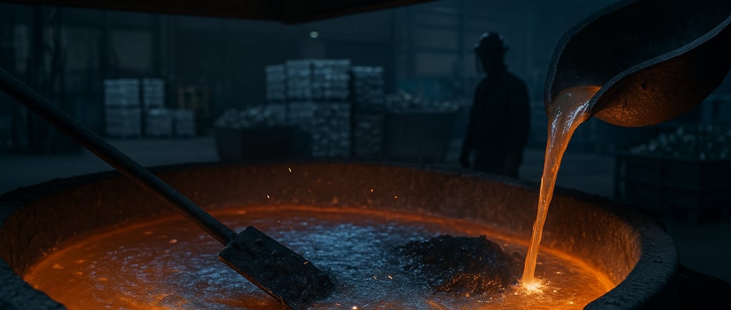
When it comes to aluminum remelt operations, flux selection is both an art and a science—one that wields tremendous influence over plant efficiency, environmental compliance, metal quality, and bottom-line costs. As the global demand for recycled aluminum intensifies and energy costs surge, plant managers, metallurgists, and process engineers need to see fluxes not as miscellaneous commodities, but as a critical aspect of their process engineering toolbox.
This deep dive explores the practical metal science and industrial reality behind flux selection for aluminum remelt. We'll scrutinize the latest process analytics, review key industrial parameters, analyze cutting-edge case studies, and demonstrate the expanded role of digitalization—all while providing an actionable framework tailored to the demands of today's dynamic foundry and remelt landscape.
What is Flux in Aluminum Remelting? [Entity: Industrial Flux]
To understand why flux selection matters, let's clarify foundational principles: Flux in aluminum remelting refers to a carefully engineered blend of inorganic salts designed to target specific metallurgical functions. Managed well, flux enables operators to tackle persistent challenges associated with melting aluminum scrap and returns, such as:
Removing Oxide Impurities: Aluminum rapidly forms a tough oxide layer, even at room temperature. These layers entrap metallic aluminum and degrade product quality unless physically or chemically separated.
Preventing Excessive Oxidation: The molten metal is prone to oxidation, increasing dross generation and material loss.
Promoting Coalescence: Smaller aluminum droplets become trapped in dross; coalescing agents in flux help aggregate these droplets back into the melt, directly increasing metal yield.
Facilitating Dross Separation: A fluid, well-formulated flux improves dross separation efficiency, simplifying downstream management and increasing recovery.
Controlling Hydrogen and Gas Pick-up: Fluxes can capture hydrogen absorbed by molten aluminum, addressing a major source of porosity defects in casting.
Enhancing Cleanliness: Some specialty fluxes target contaminants like magnesium, sodium, or alkaline impurities, safeguarding the final material chemistry.
The choice of flux—its composition, the application method, and usage rate—directly impacts metal recovery, overall melt quality, scrap utilization efficiency, and even broader sustainability metrics for the entire operation.
Facts and Figures
According to [World Aluminium](https://www.world-aluminium.org/statistics/), global aluminum demand is rising at a 3-5% CAGR, fueling higher rates of recycling and thus increasing scrutiny on melt recovery rates and dross management.
Typical dross losses without proper fluxing can range from 3% to 10% of the input, meaning tens of millions in lost material yearly for large-scale plants.
The Science of Flux Selection: Key Mechanisms [Entity: Flux Selection Process]
Effective flux selection leverages a deep understanding of several intertwined metallurgical mechanisms. Let’s break these down and examine how modern industrial science optimizes each for real-world performance.
1. Oxide Removal and Drossing Efficiency
Science in Focus:
Aluminum's relentless affinity for oxygen results in rapid oxide film formation, especially pronounced with post-consumer scrap or contaminated returns. Good flux chemistry works by reducing interfacial tension between the oxide skins and the molten aluminum, agglomerating minute metallic droplets, and enabling clean, low-metal dross separation.
Case Study:
An automotive casting facility in Germany observed dross metal content drop from 19% to under 9%—simply by switching to a tailored, potassium-aluminate-based flux blend. This improvement translated to over 500 metric tons of recovered aluminum annually, along with a measurable reduction in inclusion rates on ultrasonic inspection.
2. Melt Protection from Atmospheric Gases
Industrial Challenge:
Once melted, aluminum’s reactivity is a double-edged sword. Atmospheric oxygen and, more critically, water vapor present persistent risks—resulting in added oxides and hydrogen pick-up (the most common cause of porosity in castings).
How Flux Solves It:
An ideal flux forms a floating, stable coverage on the molten bath, forming a barrier that blocks contact with oxygen and moisture in the furnace atmosphere. For rotary and reverberatory furnaces, this protective layer becomes even more crucial due to the larger exposed surface area.
Statistical Evidence:
Plants adopting high-integrity protective fluxes report up to a 45% reduction in post-casting porosity and a 20% decrease in degassing cycle durations.
3. Gas Scavenging—Hydrogen and Beyond
Hydrogen Control:
Hydrogen solubility in molten aluminum is ~0.69 cc/100g at 700°C and drops precipitate dramatically upon solidification. Absorbing and removing this gas pre-casting is critical to prevent porosity, especially for pressure die casting applications.
Advanced Approaches:
Next-generation fluxes now combine drossing and gas-absorbing capabilities, using proprietary sodium- and calcium-based salts to enhance hydrogen capture.
4. Specialty Functions
Magnesium or Alkali Removal
For foundries processing high-magnesium aluminum alloys or dirty automotive scrap, specialized fluxes can selectively react with and remove magnesium or sodium impurities—enabling compliance with strict melt chemistry specs.
Environmental and Safety Attributes
Today’s best-in-class fluxes are engineered for minimal fume evolution, low CI2 (chlorine) emission, and improved compatibility with recycling initiatives, such as maximizing metallic return and minimizing salt-cake waste.
Parameters that Define the Flux Selection Process [Entity: Aluminum Remelt Operation]
For process engineers and plant managers, it’s not enough to “choose a flux”—you must tailor it to your operational context. Consider how these parameters define your selection strategy:
Scrap Quality
Input Variability: From old can scrap, painted profiles, to oily turnings and high-grade T-bar—each has a unique oxide and contamination profile.
Flux Matching: Higher surface oxides or paint residues demand more aggressive, sometimes multi-stage, fluxing. For cleaner input, a less reactive, lower-fume blend preserves alloy integrity and is more environmentally benign.
Melt Temperature Range
Operating Window: Industrial aluminum melts typically at 660°C, but processing may require 700–900°C. Certain sodium- and potassium-based fluxes remain active over a broad thermal spectrum, while others are tailored to narrower bands for specialty alloys.
Flux Physical State: If the flux scorches or remains unmelted, it won’t deliver. Optimal fluxes are fully molten and appropriately fluid at operating temps, maximizing batch-to-batch consistency.
Furnace Design and Mixing Profiles
Rotary Furnaces: Intensive agitation leads to rapid flux and metal interaction, demanding robust, high-durability fluxes.
Reverberatory Furnaces: Larger bath area, slower mixing; may need staged or repeated flux additions.
Induction Furnaces: Focus on low-residue, non-reactive fluxes to avoid unwanted byproduct formation.
Target Metallurgy
Alloy families (e.g., 6000, 7000-series, foundry alloys) have tight chemistries. Fluxes must avoid chemical interference—no sodium pick-up if you’re laminating, no calcium build-up for aerospace parts.
Environmental, Quality, and Cost Drivers
Waste Management: Total dross and salt cake output is tightly regulated in many regions (e.g., Europe, the US). Eco-friendly, minimized-leachate fluxes are increasingly favored.
Cost Efficiency: With energy input high, maximizing metal recovery with minimal flux input can reduce overall casting costs significantly—sometimes by more than $20 per short ton.
Part 2 — Testing Methodologies, Process Window Engineering, Yard-to-Melt Analysis, Tech Trends, and More
If Part 1 made the case that flux is a strategic lever, Part 2 shows you exactly how to prove it on the shop floor. We’ll move from principles to measurement, from “use this flux” to “engineer the window,” and from melt-bay tweaks to yard-to-melt systems thinking. No tables—just the playbook.
1) Expanded Testing Methodologies: Prove It, Don’t Guess
The fastest way to turn flux selection into money is to quantify what changes in the melt—not just what looks better in the ladle. Build a layered test stack so each method cross-checks the others.
1.1 Sampling discipline (the root of trustworthy data)
Fixed locations and times: Always pull samples from the same depths, with the same dwell time after flux addition, and at the same step in the cycle (pre-degassing, post-degassing, pre-pour).
Tooling control: Pre-heated, dry, labeled tools. Moisture ruins hydrogen readings and repeatability.
Replicates: Minimum of triplicate samples per condition; discard the first if temperature drift exceeded your ±°C spec.
1.2 Hydrogen measurement (porosity risk in numbers)
Reduced Pressure Test (RPT): Simple, cheap, and strongly predictive of porosity. Track final density, fracture surface appearance, and bifilm signatures under partial vacuum.
Density Index (DI):
DI(%)=ρair−ρvacρair×100\text{DI}(\%) = \frac{\rho_{\text{air}} - \rho_{\text{vac}}}{\rho_{\text{air}}} \times 100DI(%)=ρairρair−ρvac×100
Use DI as a live KPI for flux + degassing effectiveness. Set alloy-specific guardbands (e.g., pressure die cast foundry alloys may target single-digit DI before pouring).
Real-time analyzers: If available, inline hydrogen (e.g., thermal conductivity or partial pressure based) gives immediate feedback on flux timing and gas cover integrity.
1.3 Inclusion and bifilm control (cleanliness you can see)
LiMCA/online inclusion counting: Quantifies inclusions by size class and count in real time. Great for seeing the effect of drossing/coalescing fluxes while adjusting agitation and addition rate.
PoDFA or filtration metallography: Pull a set number of melts with and without the candidate flux; classify inclusions (oxide films, spinels, carbides) and compare area fraction.
Ultrasonic or micro-CT on cast test bars: Tracks internal porosity vs. flux regime; pairs neatly with tensile bars to close the loop from metallurgy to properties.
1.4 Dross and residue analytics (where your aluminum and salts actually went)
Dross metal content: Sieve, melt-back, or centrifugal separation to quantify metallic Al recovery potential. A good coalescing flux moves this number down sharply.
Residue fingerprinting: XRD/EDS to identify salts and oxides; ion chromatography for chloride balance; TGA for volatile content. Use it to compare chloride load and to select disposal vs. secondary recovery routes.
“Drill-and-wash” cover film test: After a fixed dwell, core the frozen cover, wash, dry, and weigh—estimates film robustness and salt usage efficiency.
1.5 Process analytics that matter every shift
Yield & loss modeling: Charge mass → tap mass → cast mass, with the dross stream massed and sampled. Attribute loss to oxidation vs. entrapment by reconciling metal-in-dross tests.
Porosity rate at QA gate: % of parts failing radiography or density checks—your gold-standard “did the flux program work?”
Cycle time & energy: Minutes to target chemistry/cleanliness and kWh/t—flux that shortens degassing and rework often wins on total cost even at a higher $/kg.
2) Process Window Engineering: From “Dose” to a Tuned Envelope
Flux isn’t a single knob; it’s a window defined by temperature, timing, mixing energy, cover depth, gas flow, and residence time. Engineer the envelope so it holds under real scrap variability.
2.1 Define the CTQs (critical-to-quality)
Melt loss %, DI %, inclusion count (per mL or per mm²), porosity rejects %, cast tensile scatter, flux consumption (kg/t), salt-cake (kg/t), fume/particulate ppm.
2.2 Map the X’s that move the Y’s
Temperature profile: Entry, peak, and hold temperature. Window example: “Active range 705–745 °C for Blend A; >755 °C increases fuming and oxide turnover.”
Flux chemistry & rate: kg/t by scrap class; set min/max and a default. Consider two-stage additions for dirty charges.
Addition timing: Pre-degassing vs. post-charge, or split dosing: 70% early (coalescence) + 30% after skimming (film rebuild).
Agitation energy: Rotary rpm, reverberatory rake pattern, or injection lance N₂ flow. Too gentle = poor coalescence; too aggressive = oxide re-entrainment.
Cover thickness: Maintain a measured salt film; too thin loses protection, too thick traps heat and wastes flux.
Residence time: Minimum soak after fluxing before skimming and degassing.
2.3 Build the window with DoE, then lock it with SPC
Fractional factorial DoE: Temperature ±, flux rate ±, agitation ±, timing A/B. Run corner points and mid-point to find curvature; optimize DI, inclusion count, and loss.
Robustness to input variability: Re-run best settings with “clean,” “average,” and “dirty” scrap mixes to ensure the window holds under real world.
SPC & alarm bands: Track DI, inclusion count, hydrogen, and loss on control charts. Set action limits tied to standardized responses (e.g., +0.5 kg/t coalescing stage, +2 min soak, adjust N₂ by +5 L/min).
2.4 “Recipe card” for operators (the shift-proof layer)
Scrap class code → flux blend + dose range.
Temperature checkpoint list.
Degassing setpoints and sequence.
Visual pass/fail for cover film and dross consistency.
Escalation path when KPIs breach limits.
3) Yard-to-Melt Analysis: Fix the Inputs, Shrink the Problem
The cheapest porosity and dross are the ones you never create. Tie your flux strategy to how scrap is bought, stored, prepared, and charged.
3.1 Scrap taxonomy and gating
Classify by oxide load and contamination: Painted profiles, UBCs, oily turnings, cast returns, extrusion clean, T-bar, etc.
Moisture & oil KPIs: Moisture < 2 %; oil < 0.5 % by mass for anything going straight to melt. Anything above gets dried/deoiled or routed to rotary with tailored flux.
LIBS/optical spot-checks: Stop magnesium and alkali surprises before they enter the furnace.
3.2 Pre-treatment that pays back
Drying/deoiling: Low-temp ovens or continuous dryers to protect hydrogen KPIs.
Decoating/pyrolysis: Rotary kiln or conveyor furnace to strip paints and lacquers; combine with an appropriate flux plan to manage the ash/oxide produced.
Briquetting turnings: Reduces surface area, oil carry-in, and helps coalescence; often lets you reduce flux rate later.
3.3 Charge-makeup rules that protect the window
Stage high-oxide scrap early with coalescing flux; finish with cleaner feed to calm the bath before degassing.
Avoid “cold-wet-dirty” charges after you’ve hit your hydrogen target.
Keep a charge map: percentage by class per heat; pair it with a flux “ladder” so operators aren’t guessing.
3.4 Logistics and handling
Covered storage, FIFO lanes, and rain avoidance protocols. A single soaked batch can blow up your DI chart for days.
Yard KPIs: inbound moisture %, oil %, paint load proxies, and rejections by vendor; use vendor scorecards to lift average input quality.
4) Tech Trends: Where the Melt Room Is Heading
Flux science is evolving alongside sensors, automation, and environmental pressures.
4.1 Flux chemistry innovations
Chlorine-lean/fluoride-free blends: Lower fume, lower salt cake leachability, designed for broader temperature windows.
Hybrid functionality: Coalescing + gas scavenging + selective Mg/Na reaction in a single blend to simplify operations.
4.2 Injection and automation
Automated feeders & lance injection: Metered dosing tied to bath temperature and live hydrogen readings; removes operator variability.
Closed-loop degassing: Control nitrogen/argon flow and rotor rpm via feedback from inline hydrogen or DI proxies.
4.3 Inline quality sensing and digital twins
Live dashboards: Overlay temperature, hydrogen, inclusion counts, and flux feed rate. Show SPC bands so corrective actions are obvious.
Model-driven windows: Digital twins simulate oxidation kinetics, gas pickup, and coalescence under different scrap mixes; recommend dose and timing before you commit metal.
4.4 Emissions and circularity
Hooding & capture: Better enclosure over rotary/reverb fluxing zones to cut particulate and fume.
Salt-cake valorization: Partnerships to recover salts/alumina and reduce landfill; flux choice can enable better downstream recovery economics.
5) Safety, Compliance, and Human Factors
Great metallurgy fails if people get hurt or compliance slips.
Moisture discipline: Never flux on wet charge; steam explosions are catastrophic.
PPE and ventilation: Chloride-bearing fumes demand fit-for-purpose PPE and engineered extraction.
Dry tools, pre-heated ladles: Avoid hydrogen spikes and violent boils.
Clear stop-rules: If DI or temperature drifts outside alarm limits, operators must pause charging and follow the recipe’s corrective steps.
6) KPIs and Targets: What Good Looks Like (tune to your alloys)
DI after degas: Stable single digits for most foundry alloys before pour.
Inclusion count: Sustained reduction trend after flux program change, validated by LiMCA/filtration metallography.
Melt loss: Meaningful drop in metal-in-dross and total loss % over rolling 30-day windows.
Flux consumption: kg/t reduced or held flat while quality improves.
Salt-cake per ton: Trending down with chemistry that enables recovery.
Porosity rejects: Month-over-month decline at QA with stable or reduced degassing time.
Cycle time/energy: Minutes and kWh/t trimmed without quality trade-offs.
7) Implementation Blueprint (90-Day Rollout)
Days 0–10: Baseline
Lock sampling SOPs; calibrate hydrogen and temperature instruments; map current KPIs by alloy and scrap mix.
Days 10–35: Window discovery (DoE)
Trial candidate flux blends. Vary temperature, dose, agitation, and timing. Log DI, inclusions, loss, and dross metal.
Days 35–60: Lock and scale
Select the top window; codify recipe cards; train operators; enable automated feeders where possible.
Days 60–90: Stabilize and extend
Bring yard controls online (moisture/oil gates, charge maps). Start vendor scorecards. Add dashboards and SPC alarms.
8) Field Notes and Tactics That Save You Headaches
Split-dose coalescence beats single big hits on dirty charges.
If DI bottoms out but porosity persists, chase inclusions—your degassing is fine; cleanliness isn’t.
Rotary furnaces tolerate “harder” fluxes; reverbs prefer lower-fume, broader-window blends with staged additions.
Don’t chase a perfect DI at the expense of cycle time—optimize the total cost per good ton poured.
Pair a new flux with a dross skimming SOP refresh; technique often gates the real yield win.
9) What to Ask Your Flux Supplier (and make them show you)
Temperature activity curve and fume profile for your furnace types.
Coalescence efficacy vs. oxide load with evidence (metal-in-dross, LiMCA/PoDFA).
Hydrogen removal synergy with your degassing setup.
Residue chemistry, salt-cake behavior, and any circularity options.
Recommended dosing ladders for your scrap taxonomy.
Case studies with before/after KPIs that match your alloys and furnaces.
10) The Bottom Line
Flux is not a bag of salts—it’s a process window and a yard-to-melt system. When you measure the right things, engineer the envelope, and control your inputs, flux turns from cost to compounding advantage: higher yields, cleaner metal, shorter cycles, fewer rejects, and an easier environmental story.
Connect
Your trusted partner for scrap metal procurement.
CONTACT
About
haroon@tdcventures.com
+1-307-655-7593
© 2025. All rights reserved.
NEWSLETTER